Capacitor and Capacitance | Best 2022
Introduction
We made mention of capacitors and capacitance in the Basics of Electrical Engineering, but there are more to know about the topic.
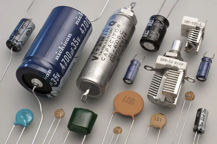
Capacitor is an electrical component that is used to store electrical energy and capacitance is the property of an electric nonconductor that permits the storage of energy as a result of the separation of charge that occurs when opposite surfaces of the nonconductor are maintained at a potential difference.

Its application can be found in energy storage devices, in rectifiers to smoothen the dc output, in radio equipments to tune frequency, in electrical filters, in oscillator circuits, in MRIs.
Since capacitors are practically used in most electric and electronic circuits, it is essential you understand the key terms involved in the concept.
Electrostatic field
Throughout the earlier topics, all we have said depict current flows through a conductor. Now, let’s go back to the basics and take a different path on charges to see where it takes us.
In the gravitational world, we isolate a body and examine the influences it has on the surrounding. That is why the most basic quantity in that study is mass. In a similar fashion, charge is like “mass” to the electricity faculty. What happens when we isolate and treat it the same way?
Just like mass, a charge has an effect whether it is at rest or moving. This is what leads to the types: static electricity and dynamic electricity.
So far, dynamic electricity is what we have talked about in recent sessions, i.e, the movement of charges which results in current flows. Let us explore what is on the other side.
Charges interact with one another, both within the same material or between materials. If we say a body is positively charged, it doesn’t necessarily mean it contains only positive charges. Rather, it is the net charge after the various positive and negative charges interact.
Static electricity is caused when the positive and negative charges in the material or between materials are not balanced. The important point to note here is that it occurs within or on the surface of a material or between materials.
About the influence, any region around the electric charge within which another point charge will experience a force of attraction or repulsion is known as the electric field. More specifically, a field around a stationary charge is the electrostatic field.
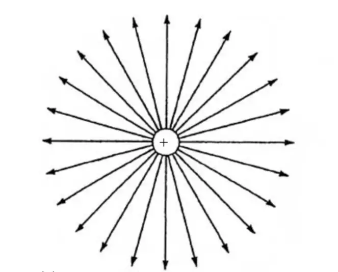
The imaginary electric lines of force are used to represent the field; the direction is from the positive charge to the negative and the closeness of the lines indicates the field strength.

To zero in, picture two parallel metal plates charged to different potentials. One will become the positive plate (indicating a high potential) and the other, negative (low potential). Due to the potential difference, an electric field will exist between them and any charge placed within the region will either be attracted to the high-potential plate or the low-potential one.

Electric field strength
Using what we know from above, we can say an electric field will exist between two parallel metal plates when we connect one of them to the positive terminal of a voltage source and the other plate to the negative terminal.
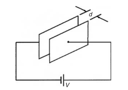
The higher the potential difference applied, the greater the electric field. Also, when the plates are close to each other, the lines of force are close to one another.
Therefore, the electric field is said to be directly proportional to the voltage applied and inversely proportional to the distance between the plates. This measure is called the Electric field strength (E), also known as the potential gradient.
E = V / d
Capacitance
We have discussed static electricity and how electric field forms. How do these relate capacitance?Using the same picture above, let’s consider the normal way and build on it.
Electrons flow from the negative terminal of the cell and current (indicating positive charges) flows from the positive terminal. Looking at the two plates, there is a disconnection. From that, we can say the circuit is opened. No current flows, but what happens really?
Since they are metallic plates, they are charged by the presence of a potential. That is, one plate will become positively charged (positive charges on its surface) and the other negatively charged (negative charges on its surface). At this point, observe what has been created. Does it remind you of any other electrical component?
Yeah! A component with a positive side, a negative side and a space in between? That’s definitely a cell.
The relationship between electrons and current is direct: current = number of electrons flowing. Therefore, it is safe to say that the charges formed on each plate are equal, but opposite. If +Q coulombs is on one, the other will have -Q coulombs.
We can also wrap our head around the above when we look at it from induction view of static electricity. When a charged material is brought near an insulator, it induces an equal but opposite charge on the other side of the insulator.
Now that we know charges are formed on surfaces of the parallel plate, our concern is how much charges are formed when a particular voltage is applied. This is what capacitance measures.
C = Q / V
When a positive voltage is applied to the pair of plates, it is known as charging. When a negative voltage is applied to the pair of plates, it is known as discharging.
Capacitors
Devices specially constructed to possess capacitance are called capacitors. In its simplest form, a capacitor consists of two plates which are separated by an insulating material known as a dielectric. A capacitor has the ability to store a quantity of static electricity.
Electric flux density
One key term in the study of capacitance is the electric flux density. Wherever there’s a field, there’s flux.
Electric flux is the imaginary influence coming from a positive 1 C charge. Therefore, Electric flux density(D) or charge density is the amount of flux passing through a defined area A that is perpendicular to the direction of the flux.
D = Q / A
Permittivity
The dielectric is that nonconducting or insulating material between the two charged surfaces. We used air for our previous example, but other can be used. Such materials should have high resistivities.
Consider the space between the two parallel plates. Within it, we said an electric field exists. We have also gotten to know electric flux is available there. Are all these interactions allowed within the space as it should? This is why the permittivity of the medium is important.
Before we look at this property, let’s first look at what the ideal situation is. Assume that space is a vacuum. Then, at any point in the field, we can assume an electric field strength E will produce its full electric flux density D. This is what is referred to as permittivity of free space (ε0).
ε0 = D / E
We now can go ahead and explore how much of that the insulating medium permits.
If the electric field strength E is constant in both vacuum and the medium, then a ratio of the flux density in the medium to the flux density in vacuum will give us the relative permittivity of our material.
εr = flux density in material / flux density in vacuum
Therefore, the absolute permittivity of the medium will be the product of its relative permittivity and the permittivity of free space.
ε = ε0 • εr
The parallel plate capacitor
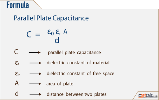
In all, the capacitance of a parallel-plate capacitor is given by
Capacitors connected in parallel and series
Parallel
Consider this example: 3 capacitors C1, C2 and C3 are arranged in parallel with a supply voltage V across them.
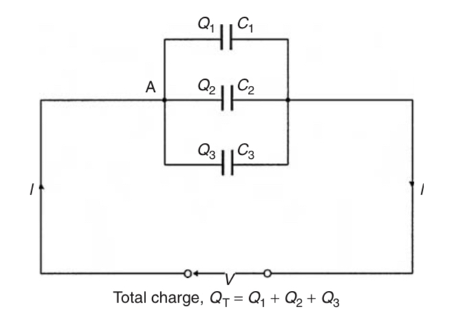
Using our prior knowledge of parallel connections, we know that different currents flow to each capacitor (say I1, I2 and I3) and the voltage across them are the same.
In that case, the charge stored on each capacitor can be determined using Q = I • t. [ Q1 = I1 • t ; Q2 = I2 • t ; Q3 = I3 • t ]. The total charge Q will be equal to the sum of Q1, Q2 and Q3.
In terms of capacitance, we said C = Q / V which is Q = C•V. Using this relationship, our total charge can be rewritten in terms of total capacitance.
C•V = C1•V + C2•V + C3•V (Remember the voltage across the capacitors are the same)
Therefore, C = C1 + C2 + C3
Series
Consider this example: 3 capacitors C1, C2 and C3 are arranged in series with a supply voltage V.
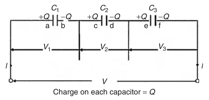
For series configuration, what we know are the same amount of current flows through the components and the voltage across each is different.
Using that, the charge on each capacitor is the same (Q = I • t) and the voltages across them will be V1, V2 and V3.
Let the charge on plate ‘a’ of capacitor C1 be +Q coulombs. This induces an equal but opposite charge of −Q coulombs on plate ‘b’. The conductor between plates ‘b’ and ‘c’ is electrically isolated from the rest of the circuit so that an equal but opposite charge of +Q coulombs must appear on plate ‘c’, which, in turn, induces an equal and opposite charge of −Q coulombs on plate ‘d’, and so on.
V = V1 + V2 + V3
In terms of capacitance, we said C = Q / V which is V = Q / C. Our voltage equation can, then, be rewritten as
Q / C = Q / C1 + Q / C2 + Q / C3 (Remember the charge on each is the same)
Therefore, 1 / C = 1 / C1 + 1 / C2 + 1 / C3
Dielectric strength
The dielectric is said to be an insulating medium. It is true that the insulator cannot conduct electricity or heat because of the high resistance it offers. However, at certain conditions, this opposition can be reduced significantly that the material begins to conduct. This is usually called insulation failure or breakdown.
One cause is the application of a high electric field strength. The maximum amount of field strength that a dielectric can withstand is called the dielectric strength of the material. Dielectric strength,
Emax = Vmax / d
Energy stored in capacitors
We know capacitors are used to store energy. So far, all we have mentioned is charges. Where is the energy stored and how does it even do that?
Let’s jog our memory once again. From basic school, we learnt energy can neither be created nor destroyed, but can be transformed from one form to another. This means the energy to be stored in the capacitor must come from another source – voltage source.
It is this electrical energy from the source that a part will be stored in the capacitor. Can energy be stored directly? No. It is stored in something that can produce the energy when we need it.
In the capacitor, the energy is stored as charges and potential difference, which can act as a voltage source to produce electrical energy.
The amount of energy stored is dependent on voltage applied and capacitance.
W = ( C • V^2) / 2 Joules
Other relations can be deduced using individual relations of the terms involved.
W = ( Q • V) / 2 Joules [for C = Q/V]
W = ( Q^2) / 2C
Practical types of capacitor
The categorization is usually based on the type of medium or material used as the dielectric. Some of the types include;
- Paper capacitors https://www.elprocus.com/what-is-a-paper-capacitor-construction-working-applications/
- Mica capacitors https://www.linquip.com/blog/what-is-mica-capacitor-2/?amp=1
- Variable air capacitors https://www.elprocus.com/what-is-a-variable-capacitor-construction-types-and-applications/
- Plastic capacitors https://www.physics-and-radio-electronics.com/electronic-devices-and-circuits/passive-components/capacitors/plasticfilmcapacitor.html
- Electrolytic capacitors https://www.linquip.com/blog/what-is-electrolytic-capacitor/?amp=1
- Ceramic types https://byjus.com/physics/ceramic-capacitor/
- Titanium oxide types