Solar Magic: Easy Printing The Sun’s Power Like Newspapers

Latest Advances in EEE – Printable Solar

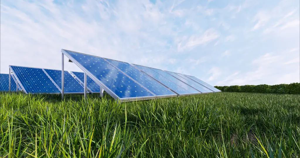
Renewable energy has become a top priority in power generation. Solar and wind are common sources engineers keep working on their technologies to make them both efficient and effectively usable. If you think you know solar panels, the instrumental component in harnessing the Sun’s energy, it’s time for an update.
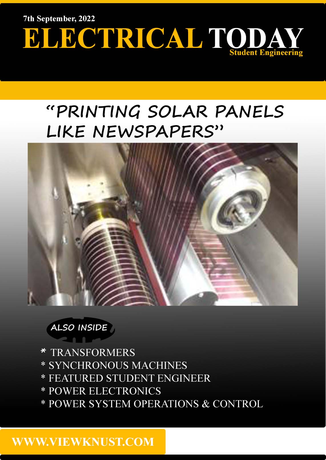
Today, solar panels can be printed like newspaper. Incredible, right? A team of Australian scientists from CSIRO (Commonwealth Scientific and Industrial Research Organization), in collaboration with the University of Monash and Melbourne, developed the printable solar panels.
Need help studying your courses? Follow who know road https://viewknust.com/academics/follow-who-know-road/
Even though the technology is yet to hit the market, the concept is fascinating and will make the industry grow faster. These scientists break down organic semiconductor polymers into ink, which has the ability to capture solar energy and convert it into electricity. This means one just has to print the ink on surfaces (plastics, steels) to make the solar panels.
Read more on the Solar technology https://www.greenmatch.co.uk/blog/2014/09/printable-solar-panels
This technology makes solar panels easy to connect and simple to replace. Once the efficiency issue is sorted out, the printable solar panels will be seen in every corner of the earth: on phones, books, laptops, shirts, cars, buildings, etc.
First Year Topic
Transformers
It is sound to assume you know about direct current(D.C) and alternating current(A.C).
With the D.C system, voltages cannot be changed; what you produce is what you get (including losses). This means that if we needed a certain voltage to be transferred to a distance, we will need cable sizes fit to carry those voltage levels and setup stations at every mile. Its efficiency and economy of operation were suspects.
A.C system, on the other hand, brought the relief engineers craved. It had properties which made it possible to use the Faraday’s Law of Electromagnetic Induction. You remember the law, right?
You can join our forum to discuss anything electrical. https://viewknust.com/forum-phronesis/
If we can get a relative movement between the magnetic flux of one side connected to our first circuit and another coil, then we will successfully induce voltage to that other side. This induced voltage can be modified (step up, down or remain same). Now, the headache engineers faced with DC transmission system were no more. The concept is written and understood, but how do we, the engineers, achieve that? Transformers!
From the above, we know our design should have two sides: one connected to our source and the other to the receiver of the transmitted power. These are called Primary and Secondary sides respectively.

As you can see, there is a coil(wound wires) at both sides. A voltage applied at one end causes alternating current to flow through the coil and, in turn, produces an alternating flux around it. The two coils are magnetically connected since they both are on a common iron core which concentrates the linking flux . When some of the flux links the second coil, electromagnetic induction occurs – voltage is induced in the second coil. Once there is voltage, any load connected to it would drawn current from it. Case closed!
It is important to note that you have to understand what the ideal transformer is and how it is adjusted in the practical world. Maybe, at another time.
Second Year Topic
Synchronous machines
There are certain key points you first need to know.
You must understand what electromechanical energy concept is about. It’s simply the conversion of electrical energy to mechanical energy or vice versa. To do that, we need both an electric field/circuit and a magnetic field/circuit (combined as electromagnetic field). Therefore, any machine that uses the concept must have both circuits.
Since an electromagnetic field is used, the two Laws of Electromagnetic Induction come into play. We already know Faraday’s one from our earlier discussion on transformers. The other is the Lenz’s Law of Electromagnetic Induction. Now, we can move on to synchronous machines.
A Synchronous machine is, first, an electrical machine and a rotating one. This means it uses the electromechanical energy conversion. What is peculiar about this machine is that its mechanical speed(speed of the rotating part) synchronizes with its electrical frequency (frequency of the voltage and current of the stationary part producing the flux) under steady-state conditions, i.e the mechanical speed is proportional to the frequency. Hence, its name is “Synchronous machine”. Once you have seen electrical frequency, you should realize it is an AC machine.
At synchronous speed, the rotating magnetic field created by the armature current travels at the same speed as the field created by the field current, and a steady torque results from the interaction of the two magnetic fields.
For a P-pole machine, the synchronous speed Ns (in rev/min.) is related to the frequency f of the armature induced voltages and currents and the number of poles P by the equation Ns = 120f / P
As mentioned earlier, for electromagnetic induction to occur, there has to be a relative movement between the flux and a coil. In electromechanical machines, we achieve this by one of these ways;
- rotating mechanically the coil through the magnetic field.
- rotating mechanically the magnetic field past the coil.
- Varying reluctance of the magnetic circuit with rotation of one part.
This brings us to the point where you know the parts of the Synchronous machines.
- Stator (stationary part)
- Rotor (rotating part)
- Slip rings or Collector rings
- Brushes and Bearings
Of these parts, the stator frame or yoke, the pole-cores, the rotor core and air gap between the poles and rotor core, form the magnetic circuit, whereas the rest form the electrical circuit. Synchronous machines have alternating currents (AC) in the stator windings and DC currents in the rotor windings.
The Stator consists of the armature windings (group of coils) and the stator frame or yoke (which concentrates the flux on the windings). Like any magnetic circuit, its yoke is laminated to prevent eddy-current and hysteresis losses. There are also spaces between the laminations for air circulation. The Stator protects the machine, supports the poles and carries the armature flux produced by the poles.
Rotor is the rotating part which causes the shaft to also rotate. It has the field windings and a core. The core is laminated and has slots to house the windings. These field windings are excited by direct current conducted to them by means of carbon brushes bearing on slip rings or collector rings. The rotor also carries damper windings.
The slip-ring is made of copper segments, and its purpose is to facilitate the collection of current from the DC excitation source to the field windings.
The purpose of brushes is to carry current from the external circuit to the commutator (this converts alternating current to direct current). They are usually made of blocks of carbon or graphite, and are rectangular in shape. The brushes should slide freely in their holder so as to follow any irregularity in the commutator. Because of their reliability, ball-bearings are frequently employed, though for heavy duties, roller-bearings are preferable.
The ball and rollers are lubricated by hard oil for quieter operation and for reducing the wear of the bearings.
Synchronous machines are broadly classified under
- Synchronous Generators (or Alternators)
- Synchronous Motors (synchronous motors operating with load attached)
- Synchronous Condensers (synchronous motors operating on no load)
Featured S.Ing.

I am Nathaniel Agyei, a member of the KNUST Electrical/Electronic Engineering Class of 2022 and happy to be your Student Engineer feature of the day.
Why you chose EE?
To be honest, I chose the EE programme because I had heard its jobs paid way more than the ordinary worker. That drew me into the course. I also realized it has more interesting applications and opportunities in almost every field, especially when electricity has become an important part of life.
What’s your overall impression on Ghana’s engineering?
On the outside, Ghana Engineering has two faces. I knew both sides before entering and yes, they are true. Even though engineering as a whole commands respect and financial benefits, the field is not spared from “the looked-downed-upon” attitude every sector faces in the country. I think I now understand why people hold that notion.
Access KNUST CoE, more specifically EE department
KNUST Engineering, in my view, has great potential to be rocking shoulders worldwide. I know it suffers what every other programme suffers under the current education system, but I’m happy, at least, about the standard it holds out there both locally and internationally.
Things you wished were different or could be added to KNUST Engineering
I personally would want the gap between lecturers and students to be close. It’s like a community where everyone is about doing only his or her job. The bond has to be there. That way, the lecturer will always involve students actively in their academia activities outside the normal lectures. This presents more opportunities for students to develop finer and better.
What you want to contribute to EE field during your career?
One vision that convinced me to choose the EE field is my ideology of individualization of power generation. It came to me when I had to stay in a household without electricity for almost 2 years. Then, I found it very convenient as people wouldn’t lean so much on the national grid. Now, it’s even a better idea as a best option for load growth management.
Third Year Topic
Power Electronics
The two terms “power” and “electronics” may help us to understand the field. Electrical and Electronics have several distinctions. Agreed? For the two terms, you will put “power” under Electrical and “electronics” under Electronics. Why do we need to have one foot in a field and another foot in a different field?
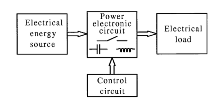
People do not use electricity. They rather use devices that use electricity. We can produce electric power as electrical engineers and the electronic engineers can design circuits that, for example, light. The lighting piece will need power to do its job, right? How do we get it to use the power we have produced?
At the junction between our electric power and the electronic circuit (electrical load), something must be present to facilitate the transition. Consider it as a team in the electronics (or load) world ready to receive the traveling power and help it settle in. This concept brought about the field “Power Electronics”. Therefore, Power Electronics is the study of electronic circuits that convert or control the flow of electrical energy (or electric power).

Now that we know we’re studying the transition team, let’s go through the instances. We already know electric power may be DC or AC. Same way, the devices may be designed to use AC or DC or both. It is the responsibility of Power Electronics to ensure that the form of the power source is usable by the device. This gives rise to the various types of power converters.
- AC – DC (Rectifiers)
- DC – AC (Inverters)
- DC – DC (DC Choppers)
- AC – AC
Power Electronics mainly contain switches and storage elements. Semiconductor switches are used to improve efficiency and storage elements (Inductors, Capacitors) to smoothen power flows.
Fourth Year Topic
Power System Operation and Control
It is important that electrical engineers know how power system operates in order to control the various levels. First thing to note is every power system begins from a generation station and ends at the consumers (loads). We can, then, define Electric Power System as the configuration of the systems and networks that deliver power to the consumers.
The stages of every bulk power system and their voltage levels include
- Generation (12 – 25 kV)
- Transmission (115 – 800 kV)
- Sub-transmission (69 – 138 kV)
- Distribution (11.5 – 34.5 kV)
- Load (240 V for 1-phase and 415 V for 3-phase)
The Generation system can be situated either at the location of use (like solar power) or far from it (like hydro power). First scenario is called local generation while the latter is bulk generation.
The transmission system supports the bulk transfer of electricity over long distances from generation facilities to distribution centres. Distribution system takes the electricity to the consumers. The differences between transmission and distribution lines are the voltage level and power-handling capability.
A consumer can be Residential, Commercial or Industrial depending on the nature of its demand. Residential customers are characterised by small, highly variable demands. Commercial customers are characterised by mid-sized moderately variable demands. Industrial customers are characterised by large consistent demands.
Subscribe to ELECTRICAL TODAY👇🏾https://viewknust.com/electrical-today-signup/
On the consumer side, a load can be either a motor load or an impedance load.
For the sake of reliability, generation must always exceed the demand by a considerable margin.Spinning reserve is the term used to describe the total amount of generation available from all units synchronized (i.e. spinning) to the system, minus the present load being supplied and losses. The reserve margin is the amount by which generation exceeds the projected peak demand, expressed as a percentage of the peak demand. The reserve margin is typically 15-20 %.
Question of Interest
There are two types of solar technologies. Name and explain how each is used to harness solar energy.