Magnetism, Magnet and Magnetic Circuit | Best 2022

Introduction
There was a time people completely treated electricity and magnetism as two different concepts without so much in common. They studied electric circuits and magnetic circuits as independent as they could. With time, we have realized they aren’t that different and both share many things in common.
One can understand electricity through the lens of magnetism and vice versa. Whatever term in one has an exact replica in the other. Enough of their likeness; the spotlight is on magnetism and its circuit in this content.
- Basics of Electrical Engineering
- Electric Circuit
- Resistance Variation
- Battery and Alternative Energy Sources
- Series and Parallel Networks
It is not so hard to infer that the concept is about magnet and its behavior. While magnetism deals with the study of magnets, magnetic circuit is clearly about arranging it with other components and exploring the behavior. Do we know what a magnet is?
A magnet is a material that can attract another material. This magical thing has the ability to attract other materials, either it is a fellow magnet or has the potential to be one. It can be temporal or permanent, but we are interested in the permanent types in this session.

When a permanent magnet is freely suspended, it positions itself in north-south direction such that the north-seeking end of the magnet is called the north pole, N, and the south-seeking end the south pole, S.
Today, the concept has many useful applications, especially when we got to know how much it related to electricity. This ranges from motors to generators to loudspeakers to relays and many others.
Magnetic field
Like electricity, magnet also has a field. The fact that it can attract does not mean from everywhere. There is a region where the magnetic force can be felt. Outside this zone, our prince’s charm isn’t seen. This area within which the magnet can attract is its magnetic field.
Since it cannot be seen, we need imaginary lines to represent the field. In magnetism, these lines are called the lines of magnetic flux. They don’t intersect, move from the north pole of the magnet to the south pole on the outside of the magnet and are then assumed to continue through the magnet back to the point at which they emerged at the north pole.
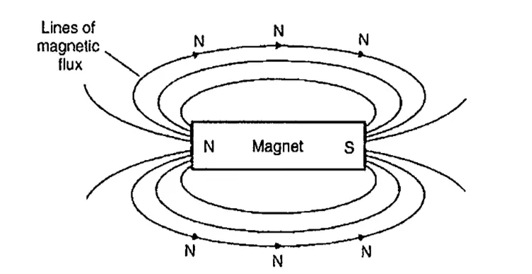
A simple law governs the attraction and repulsion under the concept: “Unlike poles attract and like poles repel”. In the picture below, we can see what happens when the laws are enforced.

The moment a S pole and a N pole was brought near each other, their lines of flux came close together and they move from the N side to the S side.
In this case, two N poles try to bring their own lines of flux and they push each other apart as the lines are seen running side by side. This is translated as repulsion.
Magnetic flux and flux density
We know the magnet produces a force which acts within a certain field. It is up to us to now understand how influential this field can be. This concern introduces us to the term magnetic flux and flux density.
In brief, the magnetic flux(Φ) measures the magnitude of the influence in the field. It shows the amount of the field coming from the magnet. Magnetic flux density(B), as can be guessed, explores the distribution of the influence per unit area of the region.
The flux is measured in Weber (Wb) and the flux density in Tesla (T). The relationship is given as
Magnetic flux density = magnetic flux / area
B = Φ / A
Magnetomotive force and magnetic field strength
The magnetomotive force (m.m.f) causes the flux we talk about. From the name alone, we can deduce it the magnetic version of “e.m.f”.
Consider a simple magnetic circuit:
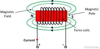
The m.m.f can be found by
Fm = N • I
where N is the number of turns and I is the amount of current flowing through the turns. The unit of m.m.f is sometimes expressed as ‘ampere-turns’. However since ‘turns’ have no dimensions, the S.I. unit of m.m.f. is the ampere.
Another important term is the field strength (or magnetizing force). It is expressed as

where L is the mean length of the flux path.
Permeability and B–H curves
In the previous session (Capacitor and Capacitance), we discussed permittivity as a term related to insulators and electricity. The world of magnetism has its own called permeability.
The magnetic flux also has to move through materials. We want to know how much these materials allow the flux through them as compared to the ideal situation in a vacuum. This leads to terms permeability of free space, relative permeability and absolute permeability.
Permeability of free space is the ratio of the magnetic flux B to the magnetizing force H in air or non magnetic materials. This is a constant.
µ o = B / H and the value is 4π × 10^(−7) H/m,
Relative permeability of a magnetic material is the ratio of the flux density in the material to the flux density in a vacuum.
µ r = flux density in material / flux density in a vacuum
Absolute permeability of a magnetic material is the product of its relative permeability and the permeability of free space.
µ = µ o • µ r
For a magnetic material, its permeability is
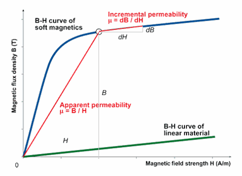
B / H = µ = µ o • µ r
The B-H curve, also called magnetization curve, plots the flux density B against magnetic field strength H.
https://www.coolmagnetman.com/magfund07.htm
Reluctance
It is the ‘magnetic resistance’ of a magnetic circuit to the presence of magnetic flux. We express it in AT/Wb or 1/Henry.

Ferromagnetic materials have a low reluctance and can be used as magnetic screens to prevent magnetic fields affecting materials within the screen.
Composite series magnetic circuits
For a series magnetic circuit having n parts, the total reluctance S is given by:
S = S1 +S2 + S3+··· +Sn
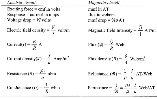
Comparison between electrical and magnetic quantities
https://www.eeeguide.com/difference-between-electric-circuit-and-magnetic-circuit/
Hysteresis and hysteresis loss
Normally, this is the part where we rush to finish the content and get over with it. However, Hysteresis is very important in our quest to understand electromagnetism, so let us slow down here and grab the fullest bite as possible.
First thing we must note is hysteresis is associated with energy loss in magnetism. In the skeleton, we can explain it as the result of a magnetic material not tracing the same path used for its magnetization during demagnetization. Let’s use the hysteresis loop to go into details.
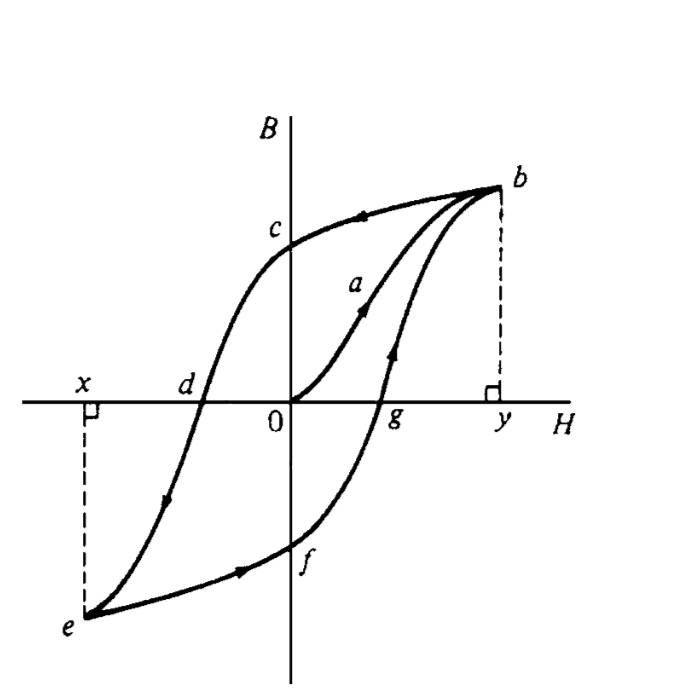
The loop is found on the B-H curve of the material. Assuming our ferromagnetic material is completely demagnetized (B=H=0), we expect B to increase as we increase H (i.e, flux density must increase with increasing field strength). This is seen as the path 0ab.
At a point, our B no longer increases or only increases very little when we increase our H. We have reach the saturation flux density. This value can be seen as the magnitude of 0b and its corresponding H at which it occurs is 0y. We have now fully magnetized the material.
We want to demagnetize the material, so we begin to reduce our H this time. In stead of the process to follow the same route, we can see it take a different path bc. This means that there is a difference in the values of B for same H for magnetization and demagnetization.
When we completely demagnetized our material, it no longer has B=H=0 like before. This time around, it has a nonzero value of B at H=0. The difference in this B and our previous B when we started completely demagnetized is known as the remnant flux density. On the graph, it is seen as 0c.
When H is increased in the opposite direction, the flux density decreases until, at a value shown as Od, the flux density has been reduced to zero. The magnetic field strength Od required to remove the residual magnetism, i.e. reduce B to zero, is called the coercive force.
Further increase of H in the reverse direction causes the flux density to increase in the reverse direction until saturation is reached, as shown by curve de. If H is varied backwards from Ox to Oy, the flux density follows the curve efgb, similar to curve bcde.
Hysteresis loss appears as heat and varies with the type of material. The energy loss as heat is proportional to the area of the loop.