Resistance Variation: A Fresh Perspective | 2022


Resistance
The concept of resistance in Electrical Engineering is a direct derivative of the term’s meaning in the real world. We know resistance, as an English word, means an opposition to a certain action.
It is this sort of opposition that limits or prevents the smooth and full effect of the intended action.
Similarly, we expect current to flow when voltage is applied to a conductor, but does the material allow the full force of the voltage to translate into current flow? The answer is a big no.
There is an opposition from the material. If nothing at all, we know “to every action, there is a reaction”. Therefore, it is safe to say that resistance is a body’s way of reacting to the voltage applied.
This property is measured in ohm. Note that all materials or bodies offer resistance, only that the magnitudes differ. While conductors have lower resistances, insulators have higher resistances.
We can find resistance of a material using
- R = ( ρ • l ) / A
where ρ is the resistivity of the material
l is the length of the material
A is the cross-sectional area of the material
- Electric Circuit https://viewknust.com/electric-circuit-intro/
- Basics of Electrical Engineeringhttps://viewknust.com/ee-101/
- Printing Solar Like Newspapers https://viewknust.com/et22-solar/
Factors That Affect Resistance
As we explore a property of an electrical material, it is important to know the various factors that affect it. Such factors include
- the length of the material
- the cross-sectional area of the material
- the temperature of the material
- the type of material
Resistance is directly proportional to the length of material, i. e, it increases with the length. Remember we need free electrons to move in particular direction for current to flow. As this happens, the electrons collide with other atoms and ions in the material. Some changes direction, others recombine and the rest continues to move. In a longer material, the collision will be more and only a few electrons will move from one end of the material to the other.
R is inversely proportional to the cross-sectional area of the material. The larger the area, the more charges can move from one end to the other. Decreasing the area means only few charges can do the movement.
Different materials have different internal structures and this affects how charges move freely within them. This difference gives materials different abilities to offer opposition to current flow. The ability is seen in the constant called resistivity.
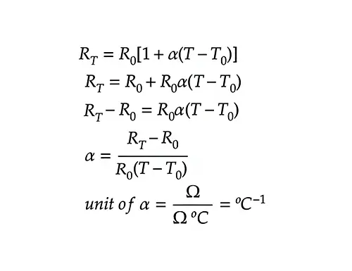
R also varies with temperature because temperature can increase the rate of collisions in the material. We see the effect in the temperature coefficient of resistance.
Don’t forget to test your knowledge on Resistance Variation https://viewknust.com/resistance-questions/
Resistivity
Like we got to know earlier, different materials offer different opposition and that characteristic is seen in the constant, resistivity.
From the R formula, we can define resistivity as the resistance of a unit cube of the material measured between opposite faces of the cube. It varies with temperature, so defined values for various materials are given at room temperature. It is measured in ohm meter (Ω⋅m).
The Standard Resistivity values of some common materials Electronics Noteshttps://www.electronics-notes.com › …Electrical Resistivity Table for Common Materials
Temperature coefficient of resistance
The idea is to determine how temperature affects the resistances of materials. Some may have R increasing when temperature increases and others will have R decreasing with increasing temperature. However, certain materials will have almost constant R at different temperatures.
To measure the relationship, we use what is called temperature coefficient of resistance. It is defined as the increase in the resistance of a 1 resistor of that material when it is subjected to a rise of temperature of 1◦C. The symbol used for this measure is α .

If the value is positive, then it means R increases as temperature increases. If the value is negative, then R of the material decreases as temperature increases. If it remains zero, it means R remains constant with the temperature change.
Resistor colour coding and ohmic values
Resistors are used all over the world in various circuits. The value of any resistor is important, since designers need to know the extent of limitations/opposition the component can offer.
To make things simple, the world has agreed to use standard ways to encode the resistance value of any resistor on itself. Two ways are discussed below
- Colour code for fixed resistors
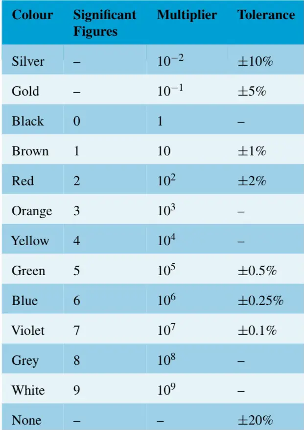
This involves the use of colors on resistors to give out their resistance values. It usually arranges the colors in a way that can be interpreted using the standard color code table.

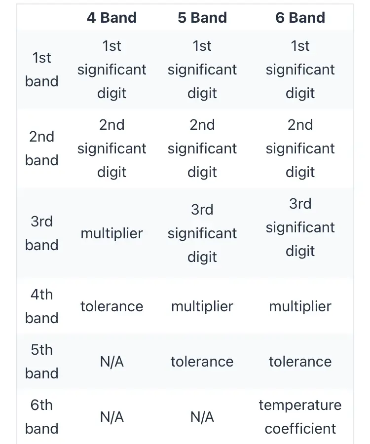
On how to read the color codes, you must note that there are 4-band, 5-band and more methods.
4-Band System
In the 4-band system, the first color represents the first significant value, second color indicates the second significant value, the third color represents the multiplier, and the fourth color shows the tolerance.
For instance, if it’s orange–red-blue-brown, this is how it will be read. The first two colors, orange-red, give us the first two significant figures. From the table, it will be 32. The third color, blue, gives the multiplier which, from the table, is 10^6. Tolerance is derived from the fourth color, so it’s ±1% for brown. In all, our resistance value will be 32 x 10^6 Ω ±1%.
5-Band System
It is similar to the 4 Band, only that a third significant figure is introduced in this system. Therefore, the first color gives the first significant figure, the second color gives the second significant figure, the third color gives the third significant figure, the fourth color shows the multiplier, and the fifth color shows the tolerance.
For example, red-yellow- white-orange-brown indicates 249 kΩ with a tolerance of ±1%

- Letter and digit code for resistors
Another way of indicating the value of resistors is the letter and digit code.

Tolerance is shown as follows
- F = ±1%
- G= ±2%
- J = ±5%
- K = ±10%
- M = ±20%
For example, when you see 6K8F on a resistor, it will be interpreted this way. From the table, K between two numbers, let’s say a and b, is read as a.b kΩ . In our case, 6K8 is 6.8 kΩ . The F shows the tolerance and it’s ±1%. Therefore, 6K8F is equivalent to 6.8 kΩ ± 1%.