Series and Parallel Networks | Best 2022
Introduction
In the previous sessions, we have learnt about voltages, currents and resistances.
- Introduction to Electric Circuit https://viewknust.com/electric-circuit-intro/
- Resistance Variation Resistance Variation: A Fresh Perspective | 2022
- Battery and Alternative Energy Sources Battery and Alternative Sources of Energy | Best 2022
Now, we are shifting our attention to how these parameters are used in circuits and how they differ in series and parallel configurations.
We know electrical circuits involve components that are connected together. With regards to the connection, how do we decide to join the parts in order to get the desired values for our parameters?
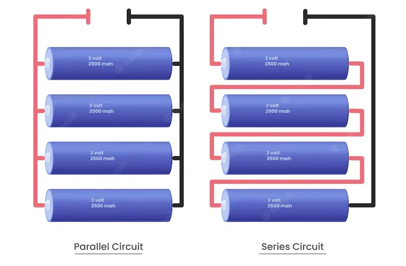
For two components in a circuit, they can be joined either in series or in parallel. Let’s consider how each arrangement appears and the dynamics in key quantities.
Series circuits
When we say components are in series, they are directly connected to each other. That is, the conductor from the first goes straight to the next without any branch or interception, and the next to the next.
Note that some cases may have branches in between, but since no current flows through those branches, we still consider the connection as in series.
Let’s consider some series scenarios
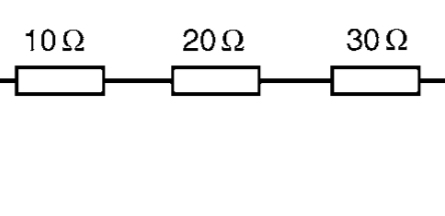
You can the 10Ω resistor is directly connected to the 20Ω resistor which also goes directly to the 30Ω resistor.
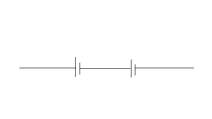
Cells are in series when the negative terminal of the first is connected to the positive terminal of the next.
Dynamics In Parameters
In a series configuration,
The current flowing is same in all parts of circuit.
The sum of the voltage drops for the various components is equal to the total applied voltage.
The total resistance is obtained by adding the values of the individual resistances.
The total e.m.f of cells (battery) is the sum of the e.m.f of individual cells.
Parallel networks
Unlike the series version, parallel configuration has branches between the components. That is, there is another path in between the connected components that can act as an alternative route for current.
Let’s consider some parallel scenarios.
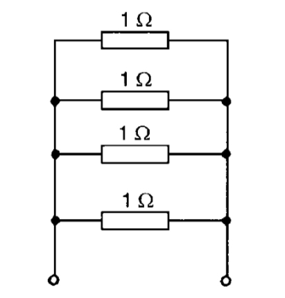
If you look at the wire connecting the first two 1Ω resistors, you’ll notice the wire at a point leads also to the third resistor. This means one can trace a closed path from the first to the third resistor without having to go through the second resistor.
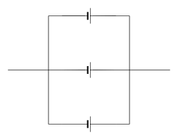
Cells are in parallel when the positive terminal of the first is connected to the positive terminal of the next.
Dynamics In Parameters
In a parallel configuration,
The voltage drop across each branch is the same.
The sum of the currents flowing through the branches is equal to the total current in the circuit.
The reciprocal of the total resistance is equal to the sum of the reciprocals of the individual resistances, i. e,
1 / R = 1 / R1 + 1 / R2 + 1 / R3 …
The total e.m.f of cells (battery) is the e.m.f of just one individual cell if they are all the same.
Potential divider
As the name implies, a potential or voltage divider is a circuit that produces an output voltage that is a fraction of the input voltage. It usually consists of two resistors in series. The voltage distribution across these resistors result in the voltage division and a voltage across only one element can be picked as the output.
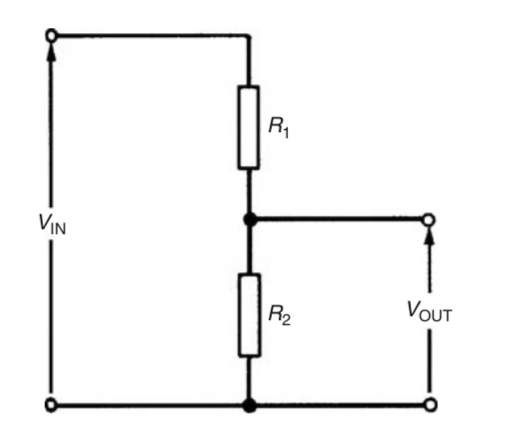
In the diagram above, R1 and R2 in series are used to divide the voltage Vin. The output voltage Vout is the voltage across the R2.
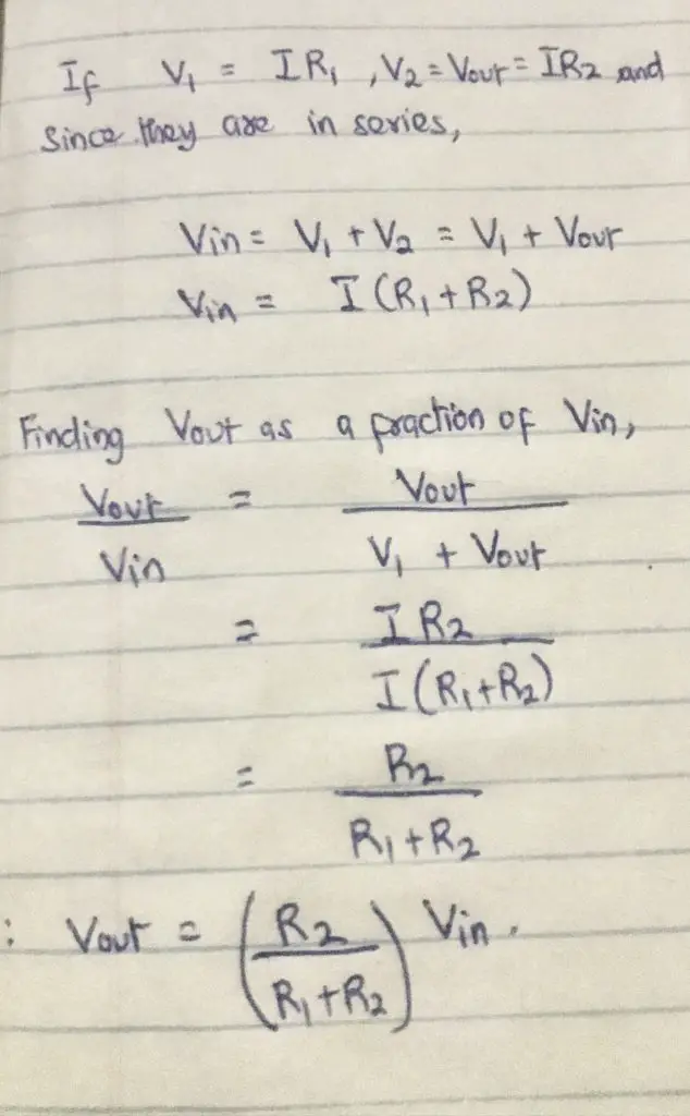
This is a way to step down voltages in circuits. A practical application is the potentiometer which utilizes a variable resistor (rheostat) as R2 to accurately measure emfs and potential differences.
Current division
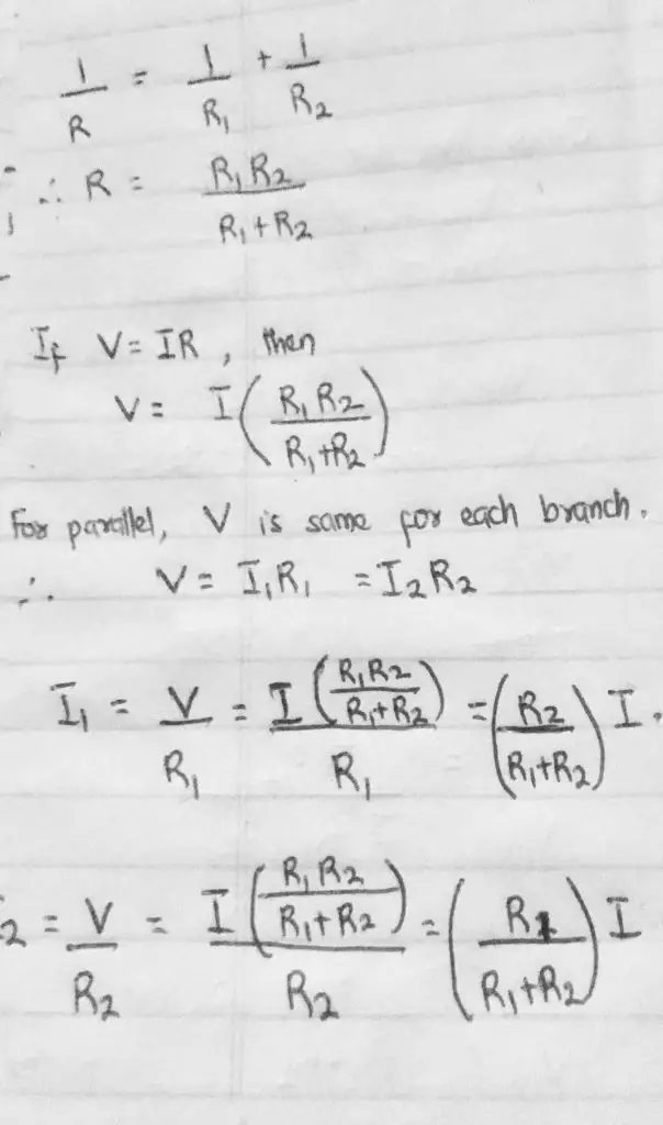
In a parallel setting, currents in different branches are not the same. How are they divided? Or do they just flow in no identifiable manner?

Assuming two resistors are in parallel. We want to explore the relationship between the currents I1 or I2 and the total circuit current I. See it in the pic below.
Relative and Absolute voltages
The voltage at a point in the electrical circuit can be written with reference to another point. This is called the relative voltage.
For instance, in this diagram, the voltage at A can be quoted with reference to (w.r.t.) D and written as Vad. In that case, relative voltage Vad will be the voltage drop across the 5Ω resistor.
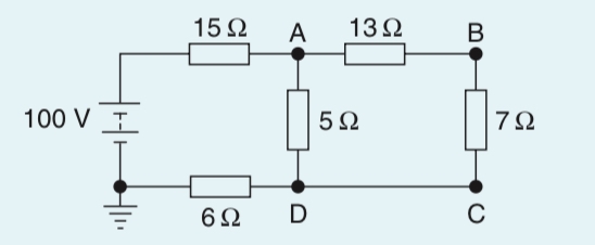
It must also be indicated whether the voltage at A w.r.t. D is closer to the positive terminal or the negative terminal of the supply source. Therefore, Vad is + 16 V or 16V +ve.
We assume it is positive if no sign is included. However, if the sign is changed to negative, then it implies voltage at D with reference to A.
Absolute Voltage
In this case, the voltage is written with reference to the earth point. What this means is that we need to find the voltage drops of all components between the point and the earth point indicated on the circuit.
Using the previous diagram, the absolute voltage at point A, Va, is the voltage drops across the 5Ω resistor and the 6Ω resistor. Similarly, the absolute voltage at point B, Vb, is the voltage drops across the 7Ω resistor and the 6Ω resistor.
In case you want to solve it for yourself, the absolute voltages are Va = 40V , Vb = 29.6 V, Vc = 24V and Vd = 24V